SECU-16™
Introduction
The
SECU-16™ module allows 8 inputs and 8 low-current relay outputs to be added to
an ADICON™ control system. The inputs may be supervised (switch closure),
analog, or 4-20mA.
Specifications
Power: Input Voltage 9 - 12V DC or AC
Input Current Max 200mA
Inputs: 8 2-wire inputs, Analog (0 – 5VDC) or Supervised
Outputs: 8 Relay outputs 24VDC, 0.5 Amp
Dimensions: 5.5”W x 3.25”L x 1.38”D
Operating
Temperature: 0ºC to 70ºC
Setup
Remove the SECU-16™ top cover.
Connect the power supply to the two screw terminals labeled POWER.
Connect the COM A and COM B terminals to the ADICON™ bus (see Figure 1).
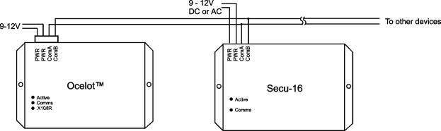
Figure 1. Typical Wiring Diagram
Three types of inputs may be used on the SECU-16™, supervised, analog, and 4-20mA. A supervised input is a passive, non-current supplying input such as a relay or switch. An analog input provides a varying voltage such as a light sensor. Input types are controlled by the jumpers as shown Table 1.
Jumpers P2 – P9 control the type if inputs used. P2 controls input 1, P3 controls input2, etc.
|
Input Type |
P2 – P9 |
|
Supervised |
2-3 |
|
4-20mA |
1-2 |
|
Analog |
Off |
Table 1. Jumper Settings
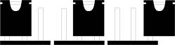
Jumper 1&2 Jumper 2 & 3 No Jumper
![]()
![]()
![]()
To use an input as a supervised input a 1K Ohm resistor (supplied) must be placed across the input as shown in Figure 2.
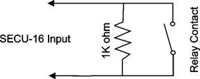
Figure 2
Operation
ADICON™ LED Codes
ACTIVE led – Slow Blink, Module has a valid address
ACTIVE led – Rapid Blink, Auto Address mode active
COMMS led – Blinks rapidly during ADICON™ communications
|
Parameter |
Function |
|
1 |
Module Address |
|
2 |
Low Analog Threshold |
|
3 |
High Analog Threshold |
|
10 |
Analog Value Input 1 |
|
11 |
Analog Value Input 2 |
|
12 |
Analog Value Input 3 |
|
13 |
Analog Value Input 4 |
|
14 |
Analog Value Input 5 |
|
15 |
Analog Value Input 6 |
|
16 |
Analog Value Input 7 |
|
17 |
Analog Value Input 8 |
Table 2. SECU-16™ Parameters
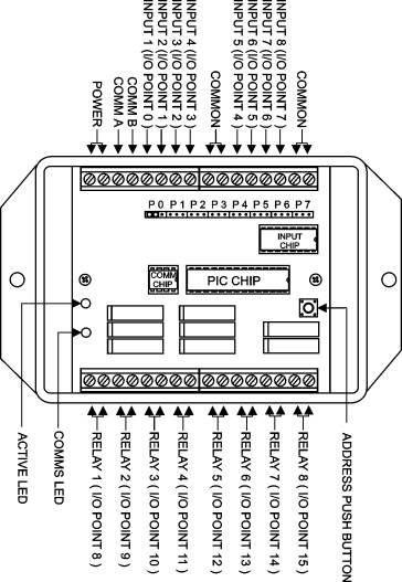
Inputs and outputs are represented by I/O points within a module. The SECU-16™ has 16 I/O points, input 1 is represented by I/O point #0, input 2 is I/O Point #1, etc. Relay 1 is represented by I/O point #8, relay 2 is I/O point # 9 and so forth.
Supervised Inputs
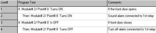
A supervised input is a switch or relay type input. The SECU-16™ will report OFF when the switch is open and ON when the switch is closed. See the example below on using a supervised input.
Analog Inputs
Analog inputs are inputs with a voltage that can vary from 0 – 5VDC such as a light sensor. The SECU-16™ will read an analog input and compare the value to the low and high threshold parameters. If the analog value is between the low and high thresholds the SECU-16™ will report that the input is OFF. If the analog input value is lower than the low threshold or higher than the high threshold the SECU-16™ will report that the input is ON.
Setting Threshold Values
Threshold and analog values are determined using the following formula:
To determine the analog reading of an known input voltage:
Analog Reading = Sensor Voltage x (256 / 5) = Sensor Voltage x 51.2
Example: If the analog voltage from a light sensor is 2 volts the analog reading would be
2 x (256/5) = 102
To determine the voltage of an analog reading use:
Voltage = Analog Reading x (5 / 256) = Analog Reading x 0.01953
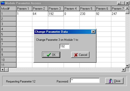
Example: If the high threshold is 192 the voltage would be
192 x 5 / 256 = 3.75V
The threshold values are stored in parameters 2 and 3 (see Table 2). C-Max™ is used to change a parameter value. Below is a sample screen of the Module parameter utility
The threshold values can also be used to perform reverse logic. Lets say for example you want an input to be OFF when closed and ON when open, such as a door sensor in a security system. This can be done by setting the low threshold to 0 and the high threshold to 128. If you wanted to have the input report OFF when open and ON when closed, set the low threshold to 128 and the high threshold to 255. This can be done with analog or supervised inputs.
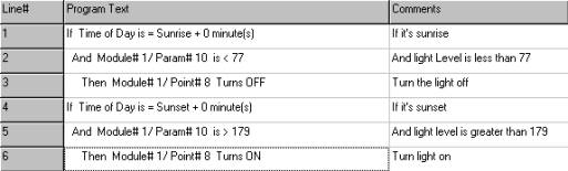
Example of Analog Input: Using a light sensor to turn outside lights on and off
First determine the threshold voltages of when you want the lights to turn on and off. For our example we will use 1.5V(77) to turn the lights on and 3.5V(179) to turn the lights off. The code example below shows how to turn the lights off after sunrise only if there is enough light and turn the lights off after dusk when dark enough. In this example, the more light on the sensor the smaller the analog reading.